Meccano Rubik's Shrine
Contents
- Contents
- Introduction
- Mechanical Design: Less Wiring, More Art
- Electronics: Use the right tool for the job
- Software
- Putting it all together
- Public demonstrations
- Publications
- Make your own Cube Solver!
- Optional: kit addition 1.
- Optional: kit addition 2.
Introduction
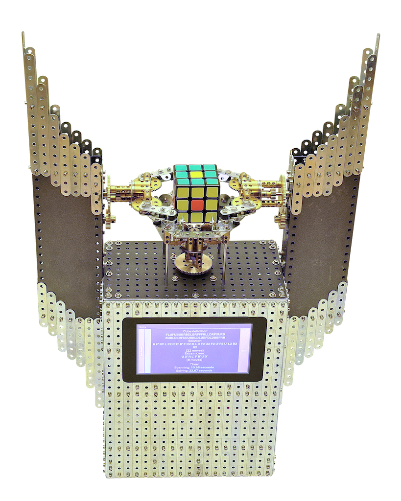 Overall look of the machine
Although our FAC Solver has gathered 120K+ views on YouTube, we felt that this was only the beginning. By the time we finished it, we had a bunch of ideas in mind that we were eager to realize. So we came up with another 3-gripper machine, this time assembled with Meccano construction set.
The model is described in Constructor Quarterly nr. 114, december 2016.
While FAC Solver was more of an experimental creation, this time we had lots of experience, so we could address fundamental weaknesses of the FAC Solver, at the same time focusing on the look and feel of the machine, making it more friendly and appealing. We didn’t want to make yet another hacky DIY machine, but something that would combine technology with decorative design, something nice to build, to see, and to own.
It took us almost half a year to finish the project: the first VirtualMEC model was made in February 2016, and we had a working prototype by June. The model is meant to pay tribute to Ernő Rubik and hence its name: Rubik’s Shrine.
Mechanical Design: Less Wiring, More Art
Having several decades of Meccano experience, Wilbert managed to design the machine that is much more compact than the FAC solver. To achieve the cleanest look possible, all the wiring and unnecessary details are hidden inside the metal body. If necessary, the PCB board and other electronics are easily accessible through the door on the back side. Moreover, the whole machine is assembled using normal Meccano parts that are available on the internet.
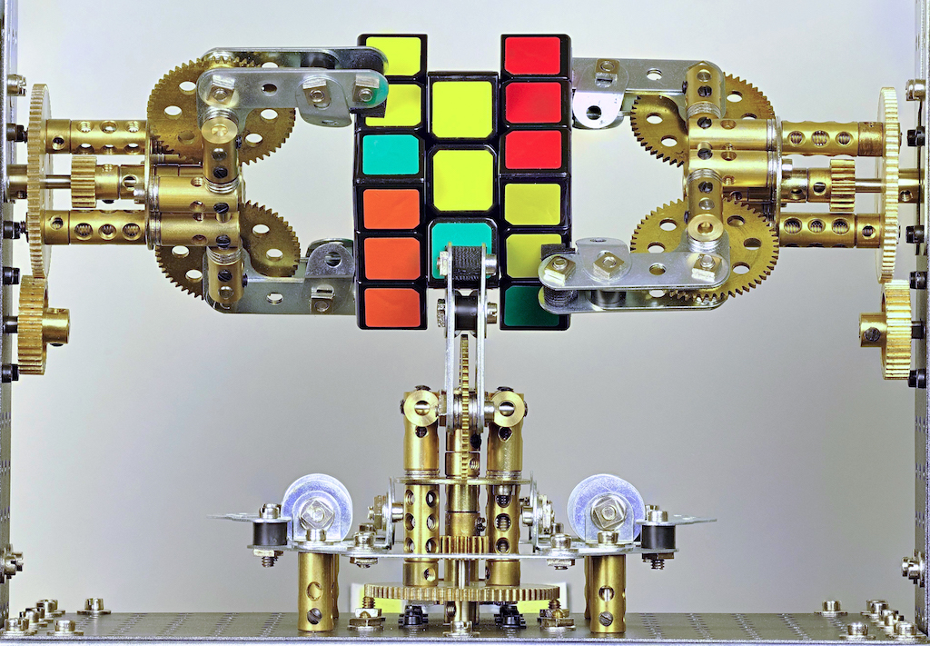
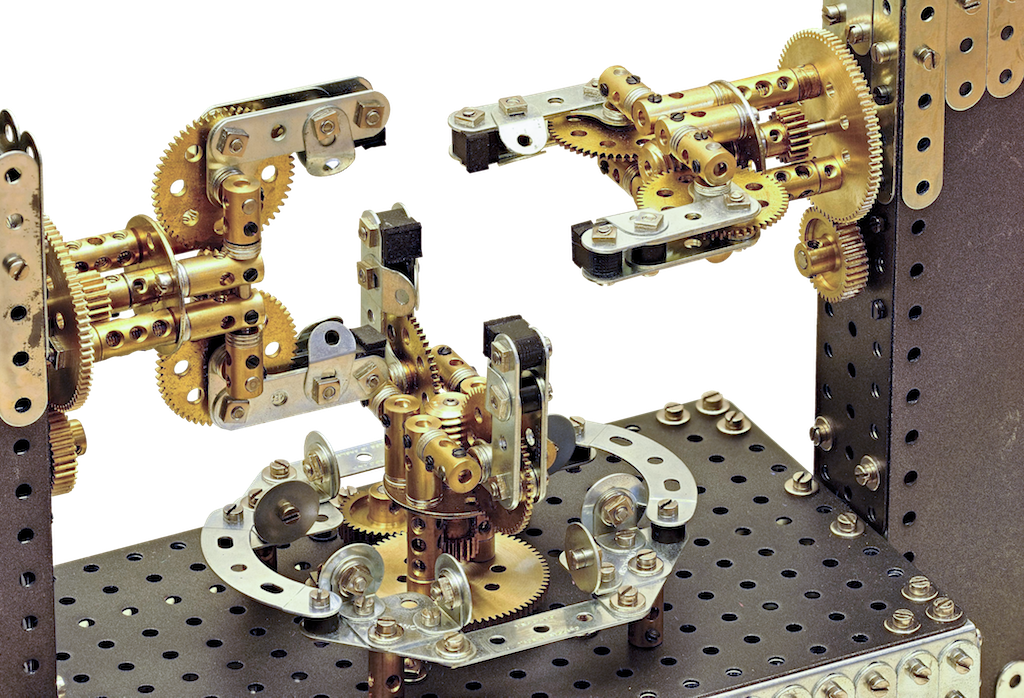
The basic setup of the machine has 3 identical grippers, mounted on a rigid frame. Each gripper is driven by 2 steppermotors. One steppermotor actuates the satellite to which an armdevice is mounted, capable of grabbing a cube. The other steppermotor actuates the wormgear for opening and closing the armdevice. Around the bottom gripper a positioning table has been designed, which can be lowered once the cube is grabbed by the 3 grippers.
 all three gripper devices are completely identical
Being very careful about the details, Wilbert made sure all parts matched each other: all original rounded shiny Meccano strips, with 3-layered custom airbrush finish on the plates. Brass gears put the final touch to the appearance of the machine.
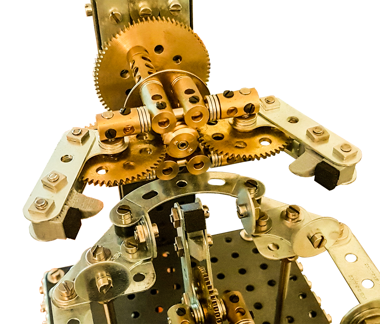
Gripper design
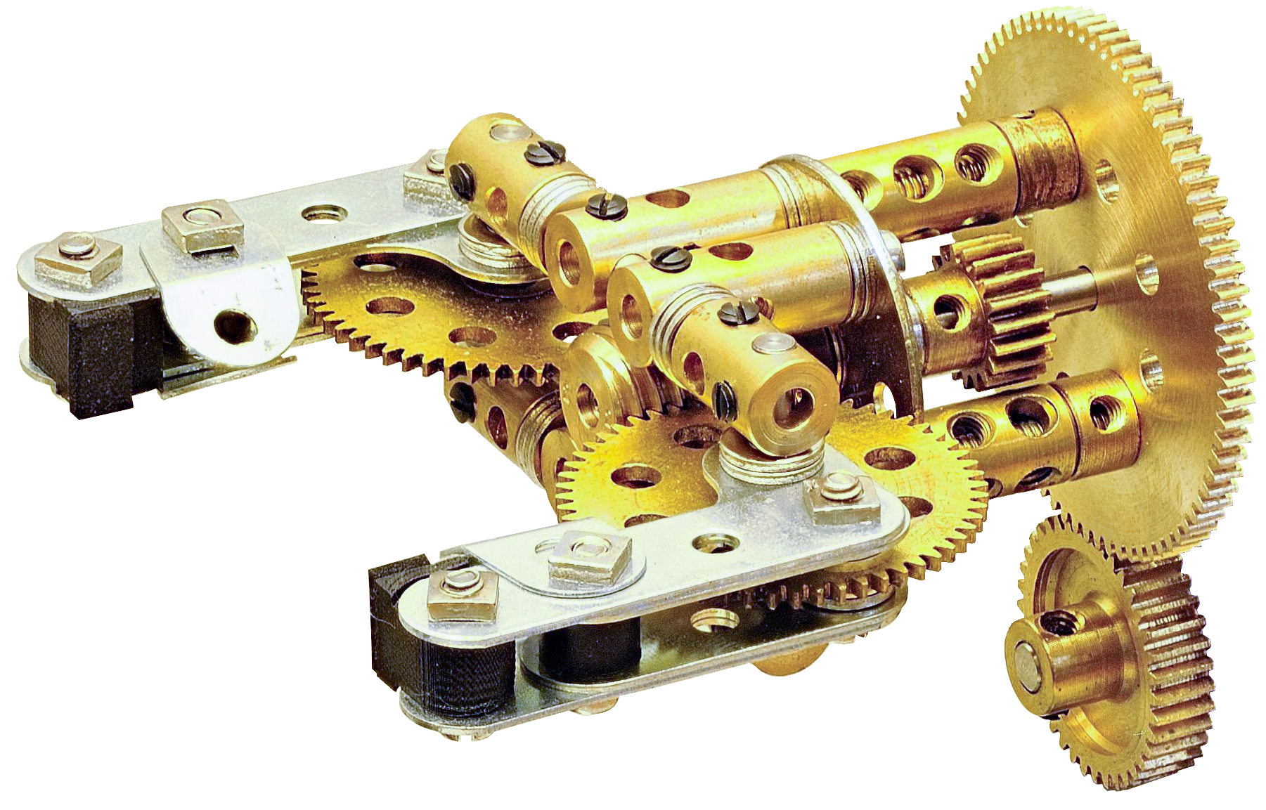
The large gear mounted on the satellite is a 76t gear (Stuart Borrill production) and engages with a 38t gear. Each arm of the armdevice is mounted on a modified 57t brass gear - similar to the 3 axle nr 27a3p, yet in brass - which is engaged by a double threaded wormgear (Stuart Borrill production). With this setup we have been able to solve a cube in 10 seconds, based on 19 cuberotations.
The arms of the gripper are mounted on the satellite through a number of carefully assembled brassparts, secured on a bushwheel at one end and the 76t gearwheel on the other end. The satellite can freely rotate around the rotoraxle to which the worm is mounted. The 19t gear in the centre of the satellite doesn’t engage with any other gear. It was merely a tool to operate the centrerotor manually during the testing phase.
The 76t/38t geartrain configuration did result in the fastest rotational speed of the gripperdevice sofar. It is obvious, that all the rotors to drive the worm must be exactly centered relative to each other and to the cube, otherwise the cube might lose it’s position relative to the grippers.
In spite of the rectangular shaped forms of the Meccano parts - one of its key characteristics - it was quite a challenge to keep the assembly of the frame strictly rectangular. Special measurement tools were needed in order to keep pure 90 degree angles between several parts of the frame. A precise assembly when it comes to the afore mentioned angles is thus essential.
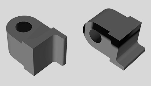 3d-printed gripper tip is the only non-Meccano part
The tip of the gripper is a 3D printed part, designed in AutoCAD and printed by a local member of the Hubs community.
To this part a small rubber strip was attached for extra friction between the gripperarm and the cube. This is the only non-Meccano part in the assembly.
UPDATE AUGUST 2018:
As per direct the grippertips have undergone a small modification. The bent fishplates are no longer necessary, which results in a more appealing design of the gripper as a whole.
 The newly designed grippertips are 3D printed. Together with the black rubber on the grippertip these parts are included within the kit.
Positioning table
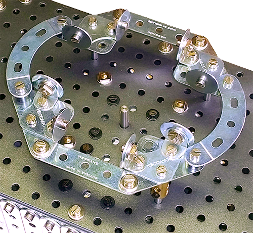 The positioning table is surprisingly simple
The function of this device is to keep the cube in a correct position relative to the grippers. Once the grippers grab the cube the positioning table is lowered all the way to the bottom.
This device of the solver is apart from the grippers probably our favorite mechanical assembly. The table is assembled with standard parts only and it’s appearance is of a disconcerting simplicity.
The free space within the table accommodates the bottomgripper and once the table is in a raised position, the bottomgripper can be opened or closed.
When the cube is placed - which dimensions is by the way based on the half inch modular - it will be put and kept in position by the 4 corner brackets (133) and the 8 large washers. The roundings of the large washers automatically will place the cube into its correct position, relative to the grippers and without the risk of damaging the cube.
This is probably the first assembly where we found a good purpose for the large washers. They are very applicable in a way we couldn’t have achieved with other Meccano parts.
Electronics: Use the right tool for the job
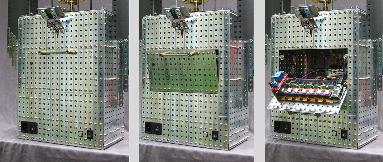 PCB board behind the door on the back side. The neodymium magnets in the corners of the opening keep the lid firmly on its place once closed.
Arduino, Teensy, and Raspberry Pi
In our previous project, the FAC Solver, (almost) everything was controlled by Raspberry Pi, including solving algorithm, color recognition, movement scheduling, and pulse generation for the stepper motors. We used Arduino only for reading the analog signal from LDRs in scanner device.
While it did work quite well eventually, it turned out to be tricky when it comes to controlling the motors. On the lower level, you can’t precisely control the time that processor gives to your process on RPi. Due to the presence of other processes, and, actually, the operating system itself, your program might be given different chunks of CPU time, which makes the generated pulse train unstable. For lower speeds, it is not a problem, but if the motor speed is high enough, it can be killing for performance: motors start hesitating. To overcome this problem, we decided to use an Arduino board for the actual motor control.
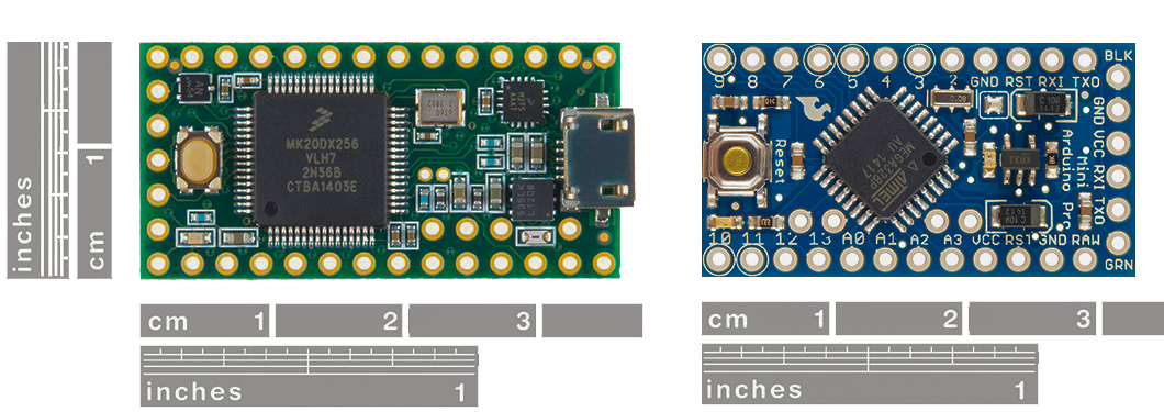 The Teensy 3 board on the left and the Arduino Pro Mini on the right: same form-factor, but the Teensy is much faster
Arduino gave us much more stable pulse train, which allowed to reach higher speeds. We also used the great AccelStepper library that made movements smoother and more reliable. We used the MIN protocol for RPi-Arduino communication.
Originally, we chose Arduino Pro Mini because it is probably the most compact one. We made the first working prototype with it, but later replaced it with the Teensy 3.2, which looks and feels almost identical, but has better performance: 72 MHz ARM processor on Teensy vs 16MHz processor on Arduino. The difference was huge (see the Memory management section).
Stepper drivers and motors
We’ve done quite a lot of research on stepper motors and stepper drivers. After some timeconsuming testings the DRV8825 driver proved to be very a good fit for the job. Designed for being used in affordable 3D printers, they are incredibly cheap and very small. And they are perfectly compatible with NEMA 14 motors that we used in this project. One minor detail though, the DRV8825 driver can get easily damaged and become useless after that.
Raspberry Pi Camera
Apart from the motor controlling, the biggest technical change in Rubik’s Shrine, compared to the FAC Solver, was the scanning part. While it was fun to play with the low-end scanner made from LDRs and LEDs, it was quite a challenge to deal with ambient light and do the color balancing. It did fit well the brutal nature of the machine but obviously was not the most modern approach.
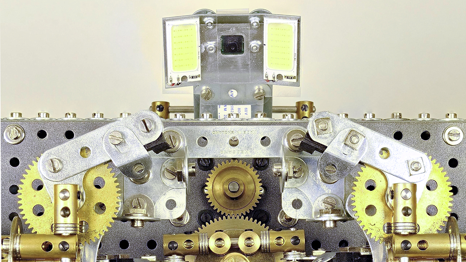 Pi Camera with flashlight lights on the sides. Flashlight is required to have stable readings under bright ambient conditions.
This time, we went fancy and used the Raspberry Pi Camera for color scanning the cube. Since it automatically adapts to the lighting conditions, it solved pretty much all of those color recognition problems (we had to use bright LED flashlight though). All we needed to do was to carefully pick the average colors from specific regions on the photos.
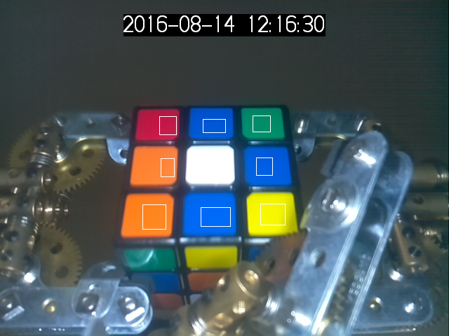 The photo of the cube with marked regions for color recognition
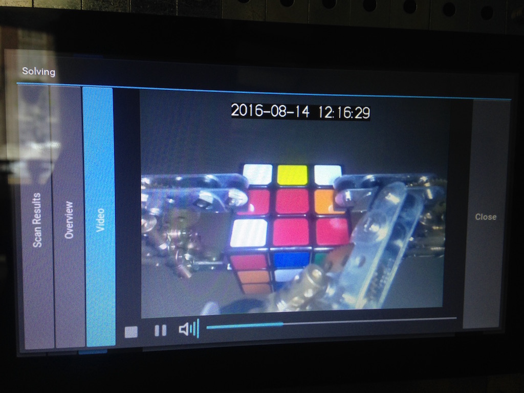
As a bonus, each run is recorded on video and available on the Archive page in the touch interface. It was also quite handy during debugging.
 Every run is captured on video
Pi Display: the Final Touch
Not so long before we started this project, Pi Foundation announced an awesome 7-inch touch screen for Raspberry Pi that perfectly fitted our model. We were pleasantly surprised that it just worked: after a couple of nights we had a nice-looking touch UI written in Kivy.
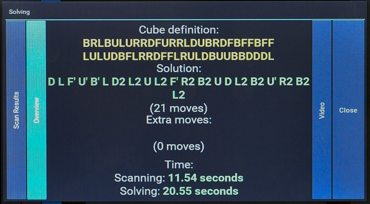 In solving mode, the result and solving time can be viewed
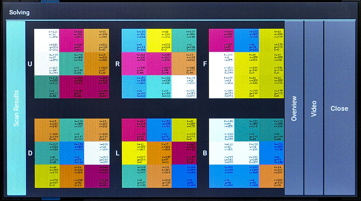 scan mode to view the scanresults
Having a touch screen, we were able to add some extra functionality to the machine. In addition to a nice presentation of the scanning and solving results, it is possible to make some pretty patterns.
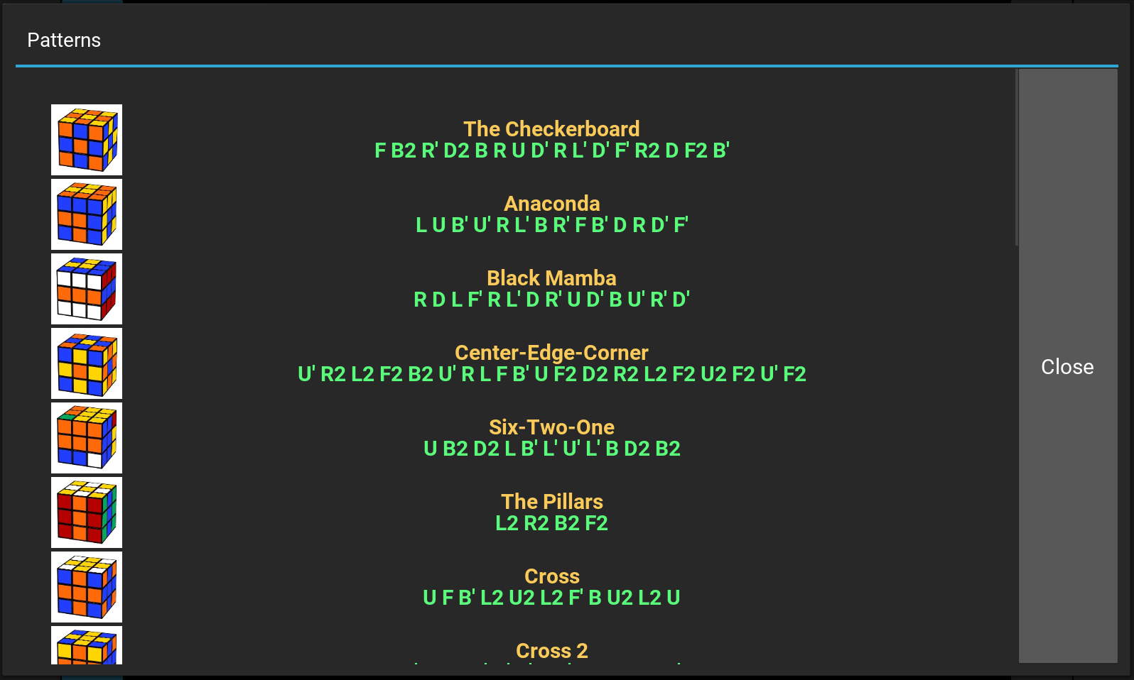 Pattern mode allows to solve the cube to some pretty patterns
We also implemented a special debug screen for manual control that practically made it unnecessary to use a laptop for testing.
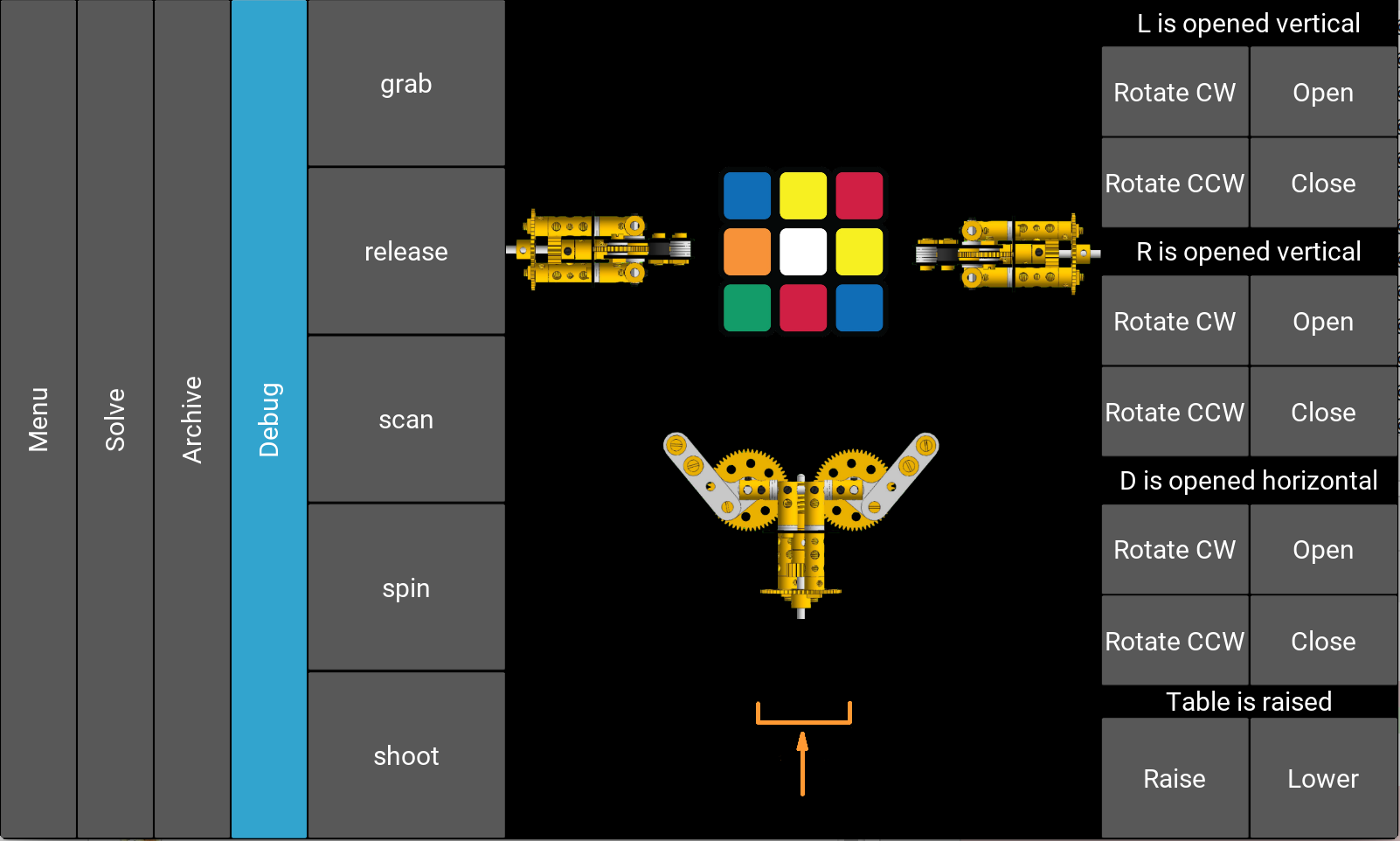 In Debug mode manual control is possible
Fine tuning
The whole machine is powered by a Mean Well 220-240V AC to 24V DC powersupply. The 24V is needed for the motorpins on the DRV8825 stepperdrivers. These drivers become pretty hot as the trimpot is adjusted to 0.7V, giving 1.4A to the output. We had to remove the adhesive tape which comes as a standard between the coolribs and the processor’s driver, and substitute it by ceramic glue. Otherwise the ribs would float away because of the heat due to it’s vertical position.
From the 24V DC circuit a bypass 12V and 5V circuit was made with voltageregulators (7800 series) for enlighting the 12V LEDs and to power the low voltage pins on the stepperdrivers. The 12V LEDs are operated from the Raspberry Pi. The Pi can only give 3,3V on it’s GPIO and for this reason a 1 channel analog level trigger had to be used to operate the LEDs from the Pi directly.
Software
Pure RPi/Python implementation of our previous Cube Solver proved to have a number of nasty caveats, so we wanted to do it right this time. We prepared for the challenge of embedded systems programming, ready to implement things from scratch to save a few bytes of RAM.
Solving algorithm
In our opinion, the best Rubik’s Cube solving algorithm at the moment is the Two-Phase algorithm by Herbert Kociemba. It is important to understand that it is suboptimal, which means it will not give you the best possible solution. But it is way faster than the optimal algorithm, which makes it more suitable for real projects like this. This will probably change in near future when we have faster computers.
For this project, we’ve made a Python/C implementation of the Two-Phase algorithm. It is freely available on GitHub.
Movements
Probably the most difficult part was the movement optimization. The solving algorithm produces a solution sequence on Raspberry Pi, which then needs to be translated into a sequence of gripper movements. Then this data has to be transferred to the Arduino board because actual electrical pulses are generated there. We wanted to make the algorithm generic so that we could use it in other machine configurations (with 4 or even 6 grippers). This added to the complexity of the problem.
Minimizing the overall solving time is not obvious. For example, in a 3-gripper setup like this, to rotate the Front side of the cube we need to rotate the whole cube first. We can rotate it around the vertical or horizontal axis. Whichever is better (leads to faster solution) depends on the current state of the grippers and on subsequent moves.
Synchronization
Generally, all grippers can move simultaneously. To do this, we need to have multiple parallel execution flows. Since Arduino is single-threaded, it has to be done with coroutine-like mechanism. On the other hand, due to the mechanical construction, some movements require the other grippers to be in specific positions, which means that parallel workers need to be able to block each other. Average solving process requires about 200 blocking operations.
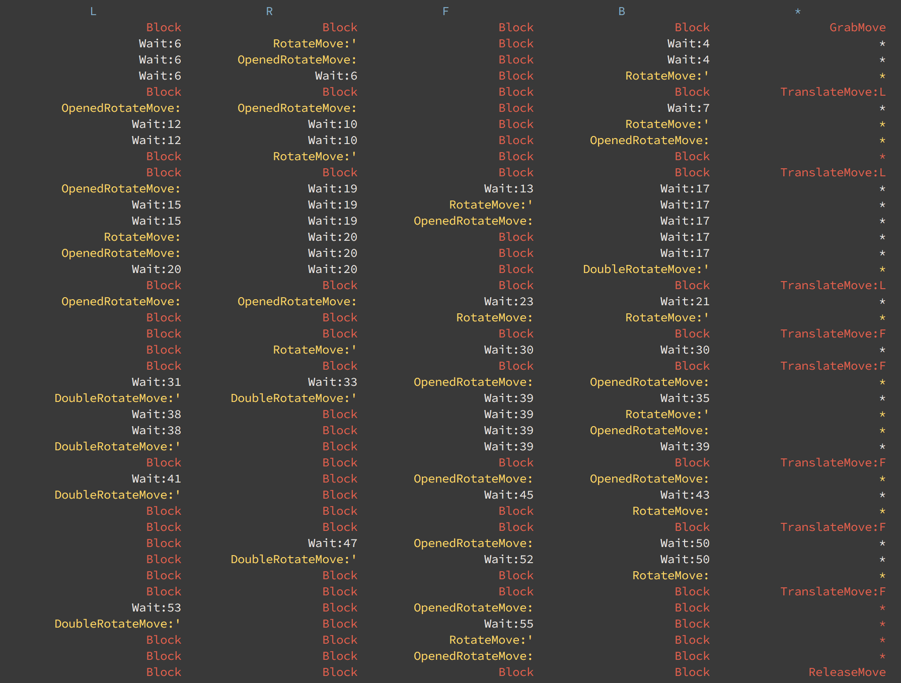 Movement scheduling for 4-gripper setup. Scheduling motor movements is quite tricky
Memory management
Arduino Pro Mini, which we used initially, has only 2KB of RAM. After initializing objects for serial communication and motor control, there are approximately 200 bytes (!) left for local variables in actual business logic. With such limited resources, we could afford to store only absolutely vital data. Everything else had to be buffered in Raspberry Pi and pushed to Arduino via serial connection during the run. Pure serial communication is quite expensive, so it was causing an additional slowdown of the solving process.
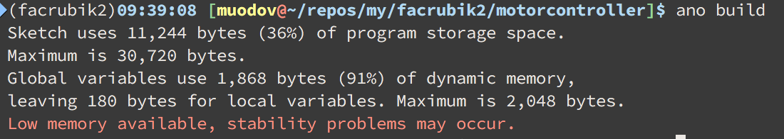 Arduino Pro Mini compilation result. We have to cope with a limited amount of memory
It is possible to write C++ code for Arduino, but the dialect is very limited: due to memory limitations it doesn’t have the C++ standard library, exceptions, etc., and in most cases it is a bad idea to use advanced tools such as dynamic allocation. It might be tough to refrain from using abstract classes with a bunch of virtual methods and dynamically allocated arrays. It is also hard to debug because you never see the exceptions: it never fails explicitly, it just starts working weird at some point, and you can only guess what went wrong, especially if you have memory-related problems. We ended up with quite hacky virtual method implementation based on switch statements and static variables, which was not that clean, but straightforward.
Later, we changed the Arduino Pro Mini with Teensy 3.2 which was a great improvement. Not only it is way faster (thanks to ARM processor), and has 64KB of RAM, but it has exactly the same form-factor as Arduino Pro Mini. We didn’t even need to change the PCB connectors!
Well, 64K ought to be enough for anybody, at least in Arduino world. With all this memory available, we could easily store information about the whole movement sequence at once. No additional serial communication + increased speed = faster and smoother solving.
Putting it all together
After all the parts are connected together, the machine is ready. The whole solving process consists of the following stages:
- Via the touch interface, user triggers the solving process
- Raspberry Pi makes photos of each side of the cube
- Photos are analyzed, and the data is sent to the Two-Phase solving algorithm
- The solution is translated into a sequence of gripper moves
- Moves are pushed to Arduino (Teensy) board via Serial interface
- Arduino, in turn, makes sure that all the motor movements are executed in the correct order, with proper acceleration and deceleration.
Public demonstrations
When the Rubik’s Shrine was almost finished, we presented it at SkegEx 2016, the annual Meccano exhibition in Skegness, England. We even managed to win the 5th prize, which is quite something considering that SkegEx is generally more about traditional mechanics rather than robotics and electronics.
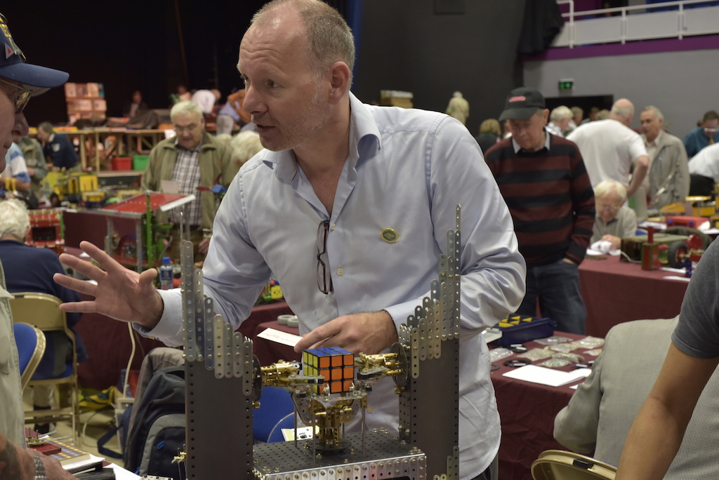 Rubik’s Shrine at SkegEx 2016
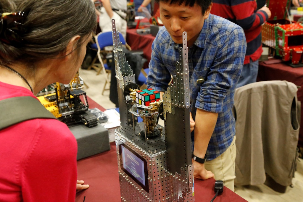 Rubik’s Shrine at SkegEx 2016
Publications
The Rubik’s Shrine has been published in following magazines and books:
- Constructor Quarterly, issue 114, december 2016
- Meccano Nieuws, issue 34.4, december 2016
- Creative projects with Raspberry Pi. Available in any bookstore or online shop
 The book about Pi
Make your own Cube Solver!
An inquisitive reader might already have enough information to make a replica of this machine. And we encourage you to do so!
However, it might also be difficult to get all the parts, since they have to be ordered from different places or you cannot buy them anywhere as we developed them ourselves. To make life easier, we decided to offer a kit with essentials for those who want to build their own version of a Rubik’s Cube Solver. The following components will be part of the kit:
- Modelplan of the Meccano Rubik’s Shrine in VirtualMEC as a .MDL file
- basic Modelplan as a .MDL file with minimal required Meccano parts for maximum freedom of design
- 23 page booklet as a PDF file, to be used as an instructable containing an explanatory of how to build the machine
- 6 NEMA 14 custom made steppermotors with 4mm shaft according to our design specifications
- 1 NEMA 17 standard motor
- pretested stepperdrivers, adjusted to their correct current output
- 6 3D printed parts for the grippertip
- professional PCB board for all the electronical hardware
- level trigger for the LED lights including LED lights
- electronic parts for the PCB. Soldering must be done by you!
- Micro SD card (harddisk) for the Raspberry Pi model 3 including preinstalled software
- Teensy V3.2 board (Arduino compatible yet much faster) including preinstalled software
- few modified Meccano parts to assemble the camera
- several non Meccano nuts, bolts and others to mount motors, PCB etc on the frame
Total price excluding packaging/transport is €500,-.
Total price excluding packaging/transport, but including a presoldered and tested PCB is €575,-.
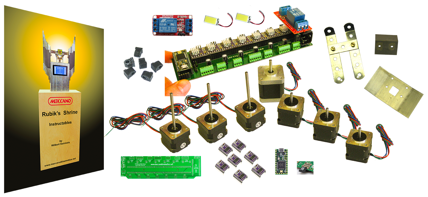 Overall look of the kit with essentials. At the left the 23page Booklet as a pdf.
Optional: kit addition 1.
We do not supply Meccano parts in order to provide maximum freedom when it comes to your personal design.
However, by the mid of 2018 it became clear, that the 76t gears and double start worms are difficult to obtain from the Internet. We have decided to offer these gears as well.
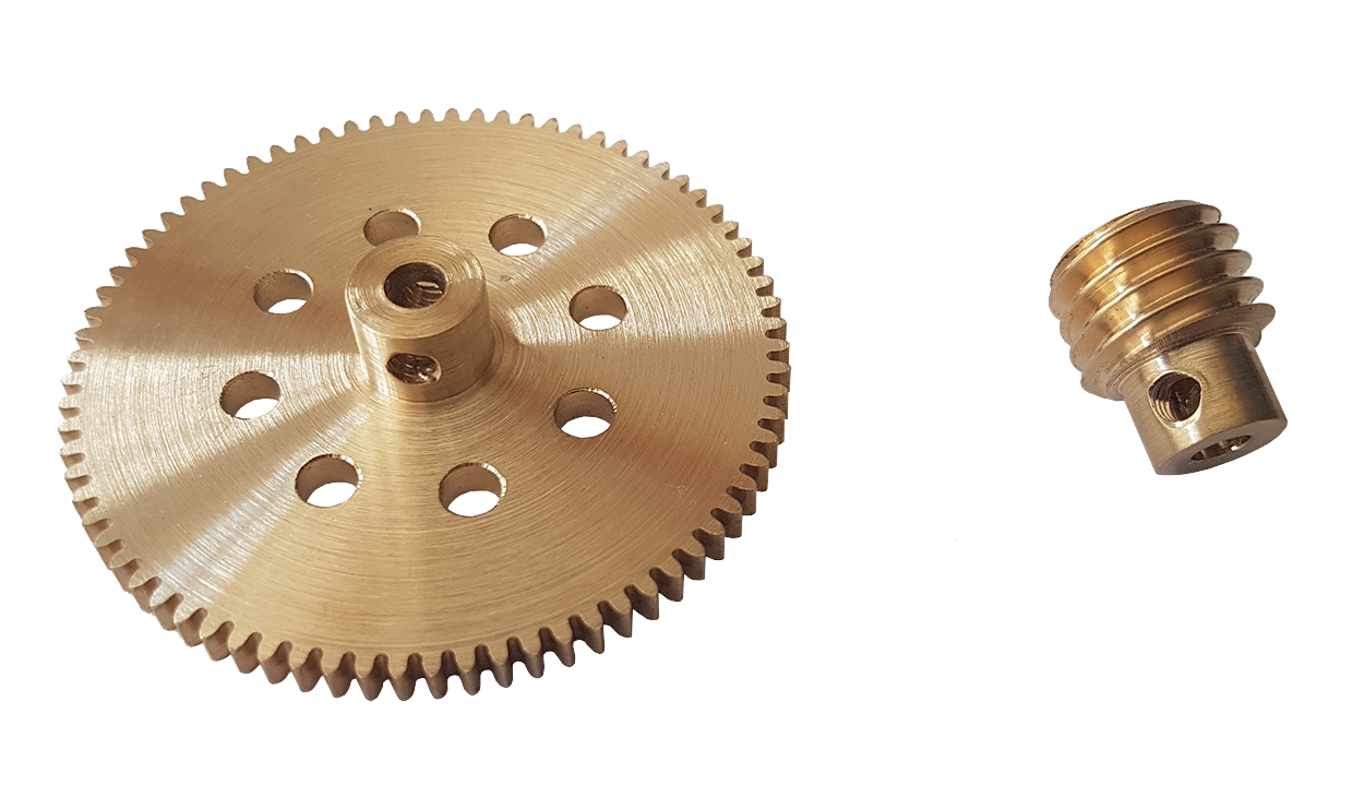 For each solver you need 3 76t gears and 3 double start worms.
Total price for 3 76t gears and 3 worms excluding packaging/transport is €82,-.
Optional: kit addition 2.
The 57t gear as used in each gripper, so 6 in total, is a modified brass gear. We can offer these modifications against productions costs.
If you are interested in having your own copy of the machine, please contact us or via: [email protected]